
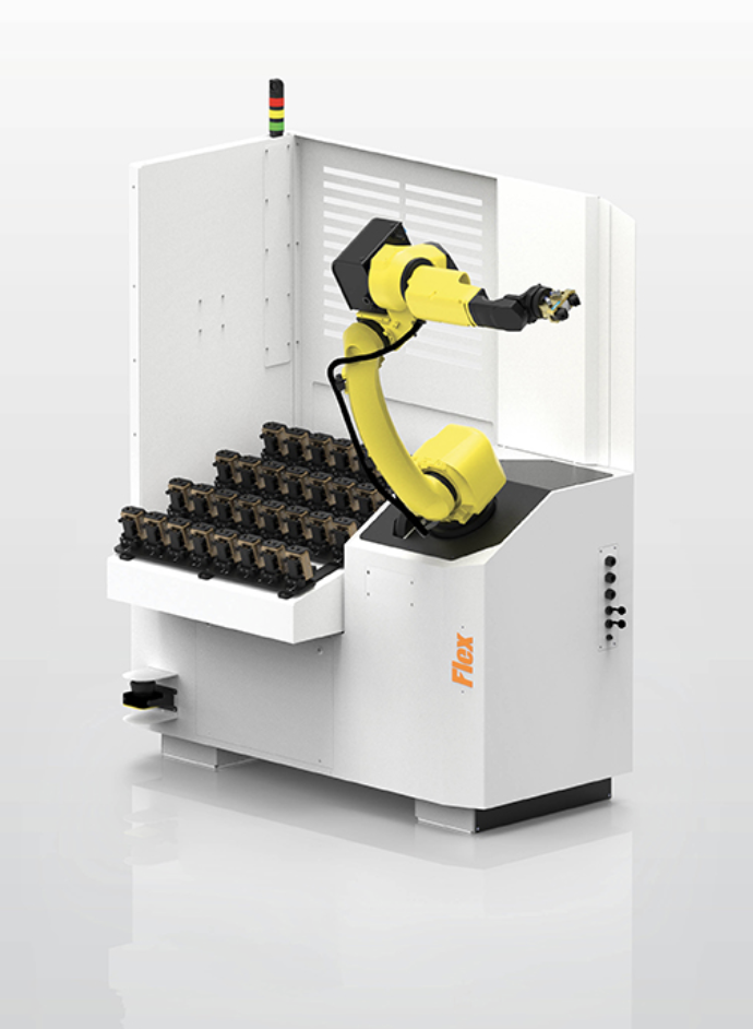
The Agile Flex 12V is a high-efficiency compact loading system designed specifically for smaller CNC machining centers. As part of Agile’s family of manufacturing automation solutions, it delivers reliable automation of the loading cycle—notably reducing manual intervention and setup time. With its automated-vise architecture and seamless integration, the 12V acts as a fully-automated CNC tool loading solution that enhances spindle utilization, supports lights-out operation, and allows engineers to focus on higher-value tasks rather than part transfers.
Agile Flex 12V Features:
Machine shops use the Agile Flex 12V CNC tool loading system to efficiently run smaller to mid-sized parts. For example, its automated-vise system supports up to 32 positions with fast change-over for frequent part transitions and minimal downtime. In addition, the system’s layout and control software simplify setup and operation, making it ideal for production environments where agility and accuracy matter.
The Agile Flex 12V integrates a 12 kg-payload Fanuc M-10iD/12 robot with a rigid, adjustable mounting system to provide precise CNC tool loading in tight production environments. In addition, the compact loading system installs directly beside most CNC machines to allow operator access as needed. This configuration delivers stable motion control, accurate part placement, and continuous part transfer during unattended operation. These manufacturing automation solutions also improve cycle consistency, support repeatable loading, and enable efficient integration into existing machining cells. As a result, it’s a seamless way to improve automated productivity in job shops.
The robot enhances process reliability through coordinated motion control and automated clamping. Each cycle is managed by the system’s integrated CNC interface, synchronizing part handling with spindle activity. This ensures smooth material transitions between machining operations without interrupting workflow. This compact loading system also maintains tight positional accuracy, making the Agile Flex 12V ideal for small-part production with precision and repeatability.
| Agile Flex 12V | |
| General | |
| Agile control software | Standard |
| User adjustable vise mounting system | Standard |
| Power supply (KvA) | 2 |
| Pneumatic pressure (bar) | 6 |
| Robot | |
| Fanuc M-10iD/12 robot (12kg payload) | Standard |
| Single 2-jaw gripper | Standard |
| Capacities | |
| No of vises (user adjustable) | 32 |
| Maximum part weight | 15lbs / 7kg |
| Safety | |
| Floor scanner | Standard |
| Integrated enclosure | Standard |
| Safety fence | Option |
The Agile Flex 12V is an compact automated vise-loading system for smaller machining-center parts. It is configured to move raw and completed workpieces between organized storage and the CNC machine while machinists remain available for setup, process control, inspection, and other skilled work. A.W. Miller Technical Sales supplies and supports Agile robotic machine-loading systems throughout New York, Pennsylvania, Maryland, Delaware, Southern New Jersey, and Quebec, with application review, cell integration, installation, training, and regional service.
A FANUC M-10iD/12 robot supplies a 12 kg payload. The user-adjustable system can stage up to 32 zero-point vises, and published maximum part weight is 15 lbs. Standard utilities are 2 kVA power and 6 bar pneumatics. Final system capacity must be confirmed with the complete part, gripper, robot reach, storage arrangement, machine interface, safety layout, cycle-time target, and unattended production plan.
Applications commonly evaluated for the Agile Flex 12V include:
The system transfers the workpiece in a zero-point vise rather than gripping the raw part directly. That approach provides a consistent loading interface for irregular or multi-sided components.
The adjustable storage system supports as many as 32 vises when part and vise dimensions allow. Capacity should be verified with the real workholding package and robot approach path.
The robot class is matched to compact machines and smaller workpieces. The combined mass of vise, part, adapter, and gripper must remain within the validated payload and moment limits.
An integrated enclosure and floor scanner support close operator access without a traditional full perimeter fence. The final safety layout must be risk-assessed with the CNC machine, doors, and surrounding workflow.
The main differences are robot class, part size and weight range, and whether parts are staged on pallets, in drawers, in zero-point vises, or in shaft nests. The correct model follows the workpiece and production flow, not storage capacity alone.
Diameter, length, nest pitch, pickup clearance, raw and finished allocation, and the number of storage layers determine usable quantity. Published maximum counts apply only to the corresponding nest and part assumptions.
It can increase available spindle hours when manual loading is the limiting factor. Output still depends on a stable machining process, sufficient tool life, reliable workholding, controlled chips, consistent raw stock, and a schedule that keeps the cell supplied.
Gripper selection depends on part geometry, surface condition, weight, exchange method, and whether raw and finished parts must be held simultaneously. Jaw sensing, pressure control, and drop prevention should be matched to the risk of the application.
Stable, repeatable cycles with predictable part presentation are the strongest candidates. Turning, milling, multi-tasking, and grinding cells can all be evaluated when the robot can access the workholding and the process can run reliably without constant manual correction.


