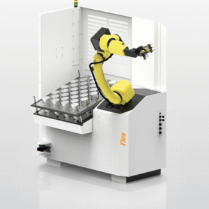

The Agile Flex 35V is a high-performance automation platform engineered to support large-part machining with precision and consistency. Designed as part of Agile Robotics’ advanced machine tool automation solutions, it combines a compact footprint with heavy-duty capacity for improved spindle utilization and lights-out productivity. Equipped with an automated-vise system, it enables rapid part changeovers and consistent clamping accuracy—allowing engineers to optimize cycle times, reduce manual labor, and achieve stable, repeatable machining performance across complex production environments.
Agile Flex 35V Features:
As one of the most capable systems in the Agile Flex lineup, the 35V is a flexible machine tool automation solution that scales production goals. It’s designed for vertical machining centers and mill-turn applications requiring both speed and strength. In addition, the automated-vise architecture simplifies part loading and eliminates operator-dependent variability, keeping productivity steady during long or unattended runs. For manufacturing engineers managing high-mix environments, the Agile Flex 35V provides a stable, repeatable foundation for continuous production and reliable performance.
The 35V features an advanced automated loading system for CNC machining centers, offering seamless part transfer between vises and machines. This plug-and-play setup reduces changeover time and ensures optimal part alignment with every load. In addition, built-in smart controls manage precise motion sequences for efficient multi-job scheduling with minimal oversight. Since the setup requires no robotic programming, operators can easily adapt it to new parts or short runs. As a result, production stays consistent while reducing non-cut time, waste, and manual handling across the entire workflow.
The Agile Flex 35V integrates smoothly with automated 5-axis machining cells, supporting complex geometries and tighter tolerances. Its automation software coordinates with CNC systems to manage part positioning and spindle access automatically. This reduces the need for manual adjustments between operations while ensuring reliable part repeatability. This automation system was designed for precision-driven manufacturers to maximize machine uptime, enhance quality assurance, and allow engineers to focus on process optimization rather than manual loading.
| Agile Flex 35V | |
| General | |
| Agile control software | Standard |
| User adjustable vise mounting system | Standard |
| Power supply (KvA) | 3 |
| Pneumatic pressure (bar) | 6 |
| Robot | |
| Fanuc M-20iD/35 robot (35kg payload) | Standard |
| Single 2-jaw gripper | Standard |
| Capacities | |
| No of vises (user adjustable) | 32 |
| Maximum part weight | 33lbs / 15kg |
| Safety | |
| Floor scanner | Standard |
| Integrated enclosure | Standard |
| Safety fence | Option |
The Agile Flex 35V is an automated vise-loading system for larger prismatic parts. It is configured to move raw and completed workpieces between organized storage and the CNC machine while machinists remain available for setup, process control, inspection, and other skilled work. A.W. Miller Technical Sales supplies and supports Agile robotic machine-loading systems throughout New York, Pennsylvania, Maryland, Delaware, Southern New Jersey, and Quebec, with application review, cell integration, installation, training, and regional service.
The standard FANUC M-20iD/35 robot has a 35 kg payload, and the user-adjustable mounting system carries as many as 32 zero-point vises. Published maximum part weight is 33 lbs, with 3 kVA power and 6 bar pneumatic requirements. Final system capacity must be confirmed with the complete part, gripper, robot reach, storage arrangement, machine interface, safety layout, cycle-time target, and unattended production plan.
Applications commonly evaluated for the Agile Flex 35V include:
The robot moves the part together with its zero-point vise, preserving a defined mechanical interface between storage and the machining center. This is useful where direct gripping of irregular stock would be less repeatable.
The storage layout can be configured for as many as 32 vises. Actual capacity depends on vise size, part overhang, robot clearance, and the space needed to prevent contact between adjacent workpieces.
The larger robot provides the payload margin required for the combined mass of the part, vise, gripper, and any adapter. Payload calculations must include the complete end-of-arm assembly rather than part weight alone.
Robot reach, door access, table position, air-blast or wash requirements, and vise seating confirmation must be developed around the specific CNC machine and fixture interface.
The quoted robot payload is not the allowable part weight by itself. Gripper, jaws, adapters, one or two handled parts, reach, wrist orientation, acceleration, and part moment must all be included in the engineered load calculation.
The system uses its specified storage format to provide repeatable pickup locations and separate or reuse positions for completed parts. Nest design, spacing, orientation, and replenishment method are developed around the actual component.
Yes, when the storage, gripper, CNC workholding, programs, and tool capacity support those parts. Mixed production should be tested as a complete schedule so a change in jaws, tools, or inspection does not become the hidden constraint.
The safety design can include an integrated enclosure, floor scanner, fence, light barrier, interlocked access, and machine-door monitoring as applicable. The final arrangement requires a cell-specific risk assessment and validated stopping distances.
A.W. Miller helps define the application, machine interface, layout, workholding, gripper, part presentation, safety, commissioning, and operator training, then provides regional service support after production begins.