
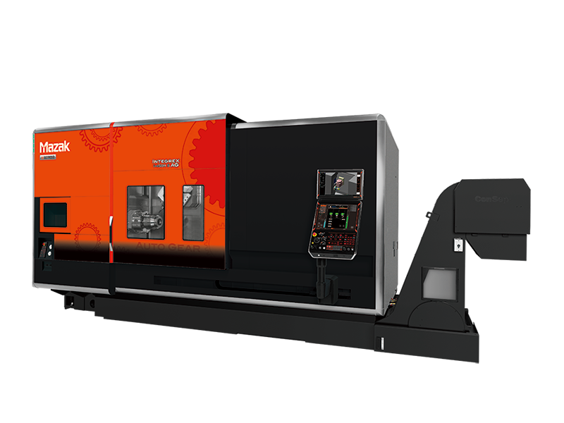
The Mazak Integrex i-250H AG Multi-Tasking machine is innovative, and engineered to deliver maximum versatility and throughput for medium to large complex parts. Merging the power of a high-powered turning center with the comprehensive functionality of a full-function machining center, it produces parts in single setups, infused with HYBRID AUTO GEAR (AG) functionality for unmatched efficiency.
Integrex i-250H AG Features:
| Model | Integrex i-250H AG, Integrex i-250H S AG, Integrex i-250H ST AG |
|---|---|
| Chuck Size | |
| Max Workpiece Diameter | 26.38″ |
| Max Machining Length | 39.8″, 59.8″ |
$1.00
The Mazak Integrex i-250H AG with the Auto Gear (AG) package is built for precision gear manufacturing. It creates a fully integrated 5-axis machining environment that eliminates redundant setups and reduces lead times. In addition, this configuration improves accuracy on complex gear geometries. The machine also delivers reliable Smooth Gear Cutting performance, making it an asset for aerospace, automotive, and precision equipment manufacturers.
As part of Mazak’s intelligent machine tool solutions, the i-250H AG combines productivity with advanced gear-cutting functions. The Smooth Gear Cutting suite supports hobbing, skiving, and milling for internal and external spur, helical, and spline gears. For example, its 240-degree B-axis rotation and dual turning spindles provide true 5-axis machining flexibility. The MX Hybrid Roller Guide System minimizes vibration, increases load capacity, and extends tool life, ensuring consistent results in demanding cycles.
The i-250H AG unites vertical turning and 5-axis machining in one platform, increasing productivity and process control. In addition, it integrates seamlessly into automated cells for lights-out production. Backed by intelligent software and rugged design, it delivers scalable precision for growing operations. In conclusion, the Integrex i-250H AG expands any shop’s machine tool solutions portfolio with efficient Smooth Gear Cutting, repeatability, and innovation for advanced manufacturing.
| Model | Integrex i-250H AG, Integrex i-250H S AG, Integrex i-250H ST AG |
|---|---|
| Chuck Size | |
| Max Workpiece Diameter | 26.38″ |
| Max Machining Length | 39.8″, 59.8″ |
| Bed length | Bed length type | 1000U |
|---|---|---|
| Capacity | Max. machining diameter (upper turret) | Φ26″ |
| Max. machining length | 40″ | |
| Main spindle | Chuck size | 8″ |
| Max. spindle speed | 5000 rpm | |
| Spindle motor (40%ED) | 22 kW (30 HP) | |
| Spindle motor (cont. rating) | 15 kW (20 HP) | |
| Milling spindle | Max. spindle speed | 12000 rpm |
| Max. torque (40%ED) | 124 N・m | |
| Max. torque (cont. rating) | 91.3 N・m | |
| Spindle motor (40%ED) | 24 kW (32 HP) | |
| Spindle motor (cont. rating) | 22 kW (30 HP) | |
| Min. B-axis indexing increment | 0.0001° | |
| Automatic tool changer | Tool shank | HSK-A63 |
| Tool storage capacity | 38 | |
| Max. tool diameter | Φ4″ | |
| Max. tool diameter (without adjacent tool) | Φ5″ | |
| Max. tool length (from gauge line) | 16″ | |
| Max. tool weight | 26 lbs | |
| Travel | X-axis | 27″ |
| Y-axis | 12″ | |
| Z-axis | 42″ | |
| B-axis | -30° – +210° | |
| Rapid traverse rate | ||
| Y-axis | 1575 IPM | |
| Z-axis | 1969 IPM | |
| Tailstock | Tailstock center | MT No.5 |
| Max. thrust force | 1573 lbs | |
| Machine size | Machine width × length | 164″ × 106″ |
| Machine height | 107″ | |
| Machine weight | 28991 lbs |
| Bed length | Bed length type | 1000U |
|---|---|---|
| Capacity | Max. machining diameter (upper turret) | Φ26″ |
| Max. machining length | 40″ | |
| Main spindle | Chuck size | 8″ |
| Max. spindle speed | 5000 rpm | |
| Spindle motor (40%ED) | 22 kW (30 HP) | |
| Spindle motor (cont. rating) | 15 kW (20 HP) | |
| Second spindle | Chuck size | 8″ |
| Max. spindle speed | 5000 rpm | |
| Spindle motor (40%ED) | 18.5 kW (25 HP) | |
| Spindle motor (cont. rating) | 15 kW (20 HP) | |
| Milling spindle | Max. spindle speed | 12000 rpm |
| Max. torque (40%ED) | 124 N・m | |
| Max. torque (cont. rating) | 91.3 N・m | |
| Spindle motor (40%ED) | 24 kW (32 HP) | |
| Spindle motor (cont. rating) | 22 kW (30 HP) | |
| Tool shank height | 1″ | |
| Boring bar shank diameter | Φ2″ | |
| Min. B-axis indexing increment | 0.0001° | |
| Automatic tool changer | Tool shank | HSK-A63 |
| Tool storage capacity | 38 | |
| Max. tool diameter | Φ4″ | |
| Max. tool diameter (without adjacent tool) | Φ5″ | |
| Max. tool length (from gauge line) | 16″ | |
| Max. tool weight | 26 lbs | |
| Travel | X-axis | 27″ |
| Y-axis | 12″ | |
| Z-axis | 42″ | |
| B-axis | -30° to +210° | |
| W-axis (second spindle) | 42″ | |
| Rapid traverse rate | X-axis | 1969 IPM |
| Y-axis | 1575 IPM | |
| Z-axis | 1969 IPM | |
| Machine size | Machine width × length | 164″ × 106″ |
| Machine height | 107″ | |
| Machine weight | 29652 lbs |
| Bed length | Bed length type | 1500U |
|---|---|---|
| Capacity | Max. machining diameter (upper turret) | Φ670 mm |
| Max. machining diameter (lower turret) | Φ420 mm | |
| Max. machining length | 1519 mm | |
| Main spindle | Chuck size | 8″ |
| Max. spindle speed | 5000 min-1 | |
| Spindle motor (40%ED) | 22 kW (30 HP) | |
| Spindle motor (cont. rating) | 15 kW (20 HP) | |
| Second spindle | Chuck size | 8″ |
| Max. spindle speed | 5000 min-1 | |
| Spindle motor (40%ED) | 18.5 kW (25 HP) | |
| Spindle motor (cont. rating) | 15 kW (20 HP) | |
| Milling spindle | Max. spindle speed | 12000 min-1 |
| Max. torque (40%ED) | 124 N・m | |
| Max. torque (cont. rating) | 91.3 N・m | |
| Spindle motor (40%ED) | 24 kW (32 HP) | |
| Spindle motor (cont. rating) | 22 kW (30 HP) | |
| Tool shank height | 25 mm | |
| Lower turret* | Number of tools | 12 |
| Automatic tool changer | Tool shank | HSK-A63 |
| Tool storage capacity | 38 | |
| Max. tool diameter | Φ90 mm | |
| Max. tool diameter (without adjacent tool) | Φ130 mm | |
| Max. tool length (from gauge line) | 400 mm | |
| Max. tool weight | 12 kg | |
| Travel | X-axis | 695 mm |
| Y-axis | 300 mm | |
| Z-axis | 1585 mm | |
| X2-axis (lower turret) | 220 mm | |
| Z2-axis (lower turret) | 1539 mm | |
| B-axis | -30° – +210° | |
| Rapid traverse rate | X-axis | 50000 mm/min |
| Y-axis | 40000 mm/min | |
| Z-axis | 50000 mm/min | |
| X2-axis (lower turret) | 40000 mm/min | |
| Z2-axis (lower turret) | 40000 mm/min | |
| Machine size | Machine width × length | 4995 mm × 2700 mm |
| Machine height | 2715 mm | |
| Machine weight | 16500 kg |
* Orthogonal lower turret
The Mazak Integrex i-250H AG is a horizontal multi-tasking center with gear-manufacturing capability for medium-small gear shafts, splined parts, hubs, and precision drivetrain components. Its configuration centers on turning, Y-axis and B-axis milling, optional second-spindle work, and gear functions, giving manufacturers a defined platform for parts whose critical features depend on controlled access, stable workholding, and repeatable datum management. As an authorized Mazak distributor, A.W. Miller helps manufacturers evaluate the workpiece, tooling, workholding, automation, installation, and long-term service requirements behind the machine. A.W. Miller Technical Sales is an authorized Mazak distributor serving manufacturers throughout New York, Pennsylvania, Maryland, Delaware, Southern New Jersey, and Quebec, with applications engineering, installation, training, and factory-certified service.
The i-250H AG brings integrated gear processing to parts that need more tool orientation and back-working flexibility than a conventional live-tool lathe provides. Machine selection should account for the complete workpiece and fixture envelope, material, spindle load, required tool reach, magazine or turret demand, probing, chip control, and automation plan. Published travels, capacities, spindle ratings, rotary ranges, tool limits, and maximum loads must be checked against the exact machine configuration and part process before purchase.
Parts and processes commonly evaluated for the Mazak Integrex i-250H AG include:
Turned, milled, and gear-related features can be sequenced without multiple machine handoffs.
An applicable second-spindle configuration can finish cutoff-side features after controlled transfer.
Gear tooling, cutting method, module or diametral pitch, pressure angle, material condition, and finishing allowance must be evaluated together. The Integrex i-250H AG configuration should be based on the required gear form as well as the surrounding turned and milled geometry.
Producing journals, bores, mounting faces, and applicable gear features in the same machine helps preserve their positional relationship. Probing and inspection strategy should be established from the drawing rather than added after the cutting process is developed.
The i-250H AG brings integrated gear processing to parts that need more tool orientation and back-working flexibility than a conventional live-tool lathe provides. The best family position is determined by the real fixture envelope, cutting load, and production plan.
Yes, when the required features fall within its turning, Y-axis and B-axis milling, optional second-spindle work, and gear functions. Parts should still be evaluated for tool access, inspection, deburring, and any operation that is better completed elsewhere.
Workholding determines accessible faces, usable travel, tool length, vibration response, and whether transfer or automation is practical. Fixture geometry must be included in every clearance check.
Material capability is driven by the selected spindle, tool interface, cutting data, coolant delivery, and rigidity. Aluminum, steels, and other alloys require different configurations and process strategies.
The machine name alone does not define the process. A.W. Miller can test the part requirements against capacity, options, tooling, automation, and regional installation and service needs.


